Button Boxes
The button box system at CFMRI contains the following components:
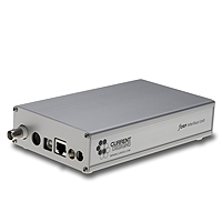
- Electronic Interface
- Fiber Optic cable
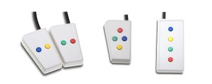
- Response Pads (2 button and 4 buttons)

SET UP
- To test the optical part of the system without a computer:
The LEDs on the side of the interface box will light when the correesponding buttons is pressed. This means that the optical part of the system is working properly. - Set the program switch for your specific application and handheld.
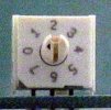
- The program switch is on the front plate of the interface box (see picture below). The switch has a small arrow which points to a number as shown below. Use a small flat headed screw driver to turn the switch to other positions.
- The interface must be reset each time the switch is changed which is done by unplugging the interface for a few seconds.
- Attach the USB cable from the Interface Box to the USB port of your computer.
- TTL Trigger: If you wish to let the scanner trigger your computer to start stimulus, please make sure that the BNC cable (labled with red tape) is connected between the interface box and the TTL/epoch port in the projection cabinet.
- Configuring the USB Port
If you have a USB port on your computer, using the fORP button pads should be as simple as connecting the USB cable between the fORP and your computer. Once connected, the fORP will appear to the computer as another keyboard, so button presses will be echoed in the active window on the display. For instance with the switch in position 0, if you are using a word processing program, you should see characters appear (r for red, b for blue, etc.) when the buttons are pressed. (In programs 3 and 5, the device will enumerate as a game pad. ) The USB input for each switch position is given below:
USB Program 0: Standard PCIn this mode the fORP is enumerated automatically as a USB HID (Human Interface Device) keyboard by the computers operating system. HID keyboards behave in well-defined ways and are widely recognized by all modern operating systems. Button presses will generate keyboard keycodes:
USB Data by Button PressButton KeycodeBlue bYellow yGreen gRed rTrigger t
USB Program 1: Standard MacThe fORP enumerates as a USB HID keyboard, with the following keycodes. The "apple + \" is needed in some Macintosh programs for the trigger.
USB Data by Button PressButton KeycodeBlue bYellow yGreen gRed rTrigger apple + \
USB Program 2: Non-Auto-Release
The keycodes are the same as program 0, but the release code is not sent until the key is released. This output can be used to give the duration of the button press. This output is useful if both press and release is of value in the experiment.
USB Program 3: Trackball
In this position the trackball enumerates as a USB HID gamepad with x, y control and two buttons. The red and green side LEDs on the interface light when the buttons are pushed. There is no initialization period with the trackball. Use:
Control Panel --> Game Controllers
USB Program 4: Standard PC Numerical
to check the trackball function under Windows.
USB Data by Button PressButton KeycodeBlue 1Yellow 2Green 3Red 4Trigger 5
USB Program 5: Joystick
In this position the joystick enumerates as a USB HID gamepad with x, y control and two buttons. The red and green side LEDs on the interface light when the buttons are pushed. To test under windows, use:
Control Panel --> Game Controllers.
USB Program 6: 8 Button Handhelds
See Appendix A for more information about the Joystick Set Up and Use.
The side LEDs will only light for right handed button pushes (1 to 4). This is a good way to distinguish between the right and left handheld.
USB Data by Button PressLeft KeycodeRight KeycodeBlue 6Blue 1Yellow 7Yellow 2Green 8Green 3Red 9Red 4Trigger 5
fORP Interface Switch Positions
Switch Position |
USB |
|---|---|
0 |
Standard |
1 |
Mac |
2 |
Non Auto-release |
3 |
Trackball |
4 |
Numeric |
5 |
Joystick |
6 |
8 Button |
7 |
Special |
APPENDIX A
Joystick notes:
This handheld enumerates as a USB HID gamepad with x, y control and two buttons. The red and green side LEDs on the interface do light when the buttons are pushed. It also works as a three button serial mouse with the trigger appearing as a third button.
Joystick Set Up: The joystick handheld has an initialization period of 5 seconds when the interface is plugged in. During this time the joystick should be on a level surface with one of the center pads in place. It should not be moved. The firmware reads the light levels in the position and uses it as the center. If its movement appears to be erratic or off center, reset the joystick by unplugging the power for a few seconds and reinitialize it more carefully. The joystick (HH-Joy-4) handheld has both a finger stick and hand grip. To use the hand grip slide into place over the finger stick. There two different centering pads: the gray pad is for use with the finger stick. The black pad provides more resistance and is for use with the hand grip. Use the o-ring to keep the pads in place.
Trackball notes:
The Trackball handheld enumerates as a USB HID gamepad with x, y control and two buttons. The red and green side LEDs on the interface do light when the buttons are pushed. The trackball works best with a light touch. The ball can be removed for cleaning. Try to keep the trackball as clean as possible, because any build up of dirt and dust on the ball and internal parts will impede its movement.